

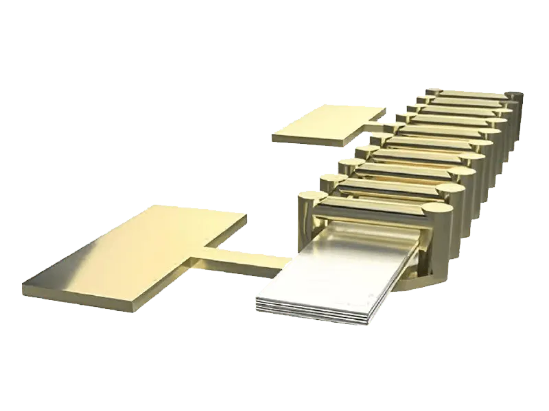
Silicon Inductor

Product Center

Silicon capacitors, silicon resistors and silicon inductors, with customization from standard selection to dimensions, parameters and packaging.

Home / Products / Silicon Inductor

Silicon Inductor

Coupling inductance series - Breaking through the magnetic core saturation bottleneck for kiloampere-level AI power supply

A thick-copper winding structure with a shared closed nano-laminated magnetic core. Anti-phase 180° excitation actively cancels DC flux, providing 4.5–10 A per-phase saturation current in an ultra-compact footprint for kilowatt-class AI GPU/XPU in-package vertical power delivery (VPD) and CoWoS + HBM power systems.

  • Active DC flux cancellation
  • 4.5–10 A per phase
  • Excellent high-frequency performance
  • On-chip integration, only 50–75 μm added
Silicon Inductor

Specifications

1–100nH/phase · 4.5–10A/phase

ParameterValue
Inductance range1–100 nH / phase
Q value> 10 @ 10–200 MHz
DC resistance (DCR)5–200 mΩ
Saturation current (Isat)4.5–10 A / phase in inverse-coupled mode
Thickness range50–75 μm added on-chip; 200–250 μm for discrete devices
Operating frequency10–200 MHz
Operating temperature−55 to 150°C
★ Key metriccurrent density > 4 A/mm²

Features

Coupled inductor · High current density · On-chip integration

Active DC flux cancellation breaks the saturation bottleneck

A single inductor accumulates unidirectional DC flux and saturates at high current. Coupled inductors use anti-phase excitation (I1 = −I2), so the DC fluxes from the two windings cancel inside the core. Saturation current is 2–5× higher than with a single inductor, which is the key to carrying high current in a small footprint.

4.5–10 A per phase supports kilowatt-class VPD

In inverse-coupled operation, each phase reaches a saturation current of 4.5–10 A and a supply current density above 4 A/mm², supporting 1500 A–3000 A+ in-package vertical power delivery.

Excellent high-frequency performance up to 100–200 MHz

Q > 10 from 10–200 MHz and an operating frequency range of 10–200 MHz extend the usable band to twice that of a single inductor (10–100 MHz), matching the trend toward higher switching frequencies in AI power delivery.

On-chip integration adds only 50–75 μm

The copper-in-magnet (CMC) / magnet-in-copper (MCM) 3D helical thick-copper structure with laminated ferromagnetic films is co-packaged at wafer level. On-chip thickness increases by only 50–75 μm (200–250 μm for discrete devices). Operating temperature: −55 °C to 150 °C.

Applications

AI GPU / XPU in-package vertical power delivery (VPD)

1500 A–3000 A+ current requirements; vertical power architectures are extremely sensitive to height and volume, and coupled inductors trade flux cancellation for higher current density.

CoWoS silicon interposer with HBM power delivery

High-density multiphase power delivery at interposer level, shortening the power path.

Why Coupled Inductors

Item Single Inductor Coupled Inductor
Saturation capability Limited by unidirectional DC flux accumulation; saturates easily Active DC flux cancellation; Isat 2–5× higher
Saturation current 0.2–3 A 4.5–10 A per phase
Operating frequency 10–100 MHz 10–200 MHz
Key metric Inductance density: 100–150 nH/mm² Current density > 4 A/mm²
Positioning Single-phase energy storage; high-reliability applications such as optical engines/aerospace High-current AI power delivery

Coupled inductor solutions for in-package vertical power delivery, with customization of inductance, phase count, size and package. Contact us for datasheets or engineering sample evaluation.

FAQ

FAQ

What are the operating frequency and Q value?

Coupled inductors operate from 10–200 MHz with Q > 10 at 10–200 MHz; single inductors cover 10–100 MHz. Compared with conventional wire-wound inductors, the silicon-based thin-film magnetic core has lower losses at high frequencies, making it better suited to high-frequency switching power.

How much thickness does a silicon inductor add?

The on-chip integrated form adds 50–75 μm; the discrete form is 200–250 μm. This thickness budget is a key parameter to consider early in advanced packaging design.

Why can coupled inductors handle higher current?

The key is 180° anti-phase excitation (I1 = −I2). The DC flux from the two windings cancels in the shared magnetic core, preventing saturation from DC bias. The saturation current is 2–5× higher than a single inductor, reaching 4.5–10 A per phase.

What applications are silicon inductors primarily aimed at?

The current focus is coupled inductors for kilowatt-class AI GPU / XPU in-package vertical power delivery (VPD) and CoWoS + HBM power. Single-inductor versions are also suitable for standalone power in CPO optical engines and high-reliability aerospace microsystems.

Do you have automotive-grade products?

The full product line covers AEC-Q200 certification requirements. Silicon capacitors, inductors, and resistors all have automotive-grade capability and can be used in automotive electronics and LiDAR.

Can you support system-level joint validation?

Yes. Launchip can work with your application engineering team to build a test platform and evaluate device performance in the real system. This is a key way we advance new applications.

How do I request samples?

Contact the relevant sales owner directly (different contacts for optical communications, LiDAR, and high-frequency power / chip silicon capacitors).

Collaboration and Contact

Talk with our application engineering team about 3D silicon capacitors, silicon inductors and silicon resistors for AI computing, optical communications, LiDAR and other demanding applications.

Contact Us
Technical DocumentationTechnical DocumentationEngineering SamplesEngineering SamplesApplication ValidationApplication ValidationProject SupportProject Support